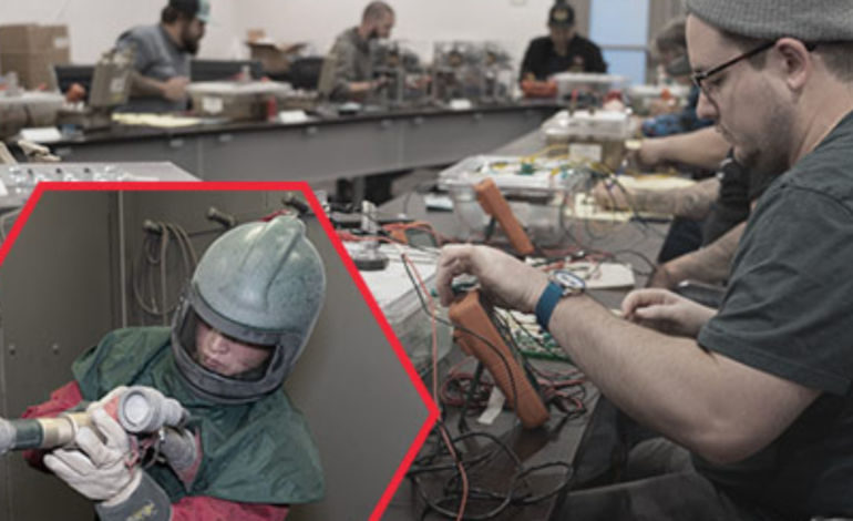
Fundamentals of Rectifier Operation, Monitoring, and Maintenance
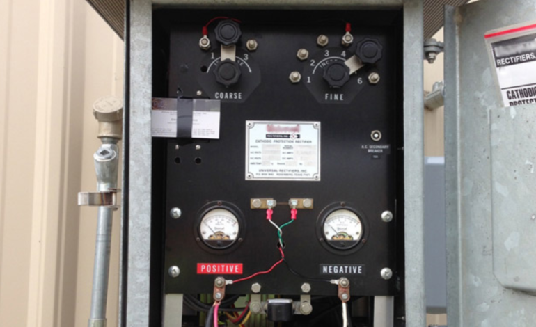
CATHODIC PROTECTION · RECTIFIERS
A rectifier is an electrical device that converts alternating current (AC) into direct current (DC). In impressed current cathodic protection systems, rectifiers provide the DC power used to help protect metallic structures from corrosion.
Because an impressed current cathodic protection system depends on a reliable power source, rectifier monitoring and maintenance are important parts of maintaining corrosion-control performance. Routine inspection can help identify outages, electrical problems, environmental damage, and other conditions before they interrupt system operation.
ELECTRICAL SAFETY FIRST
Rectifier inspection and maintenance should be performed by qualified personnel.
Follow applicable electrical-safety requirements, company procedures, the rectifier manufacturer’s instructions, and required personal protective equipment. De-energize equipment when required before troubleshooting or servicing internal components.
AT A GLANCE
Rectifier fundamentals
- Galvanic CP uses more active metals to provide protective current.
- Impressed current CP uses an external DC power source.
- Rectifiers convert AC to DC for many impressed current systems.
- Routine monitoring matters because outages can interrupt protective current.
- Common concerns include power surges, loose connections, failed components, damaged leads, overheating, and environmental exposure.
IN THIS ARTICLE
Cathodic protection systems · How rectifiers work · Monitoring · Maintenance · Common problems · Key takeaway
How Cathodic Protection Helps Preserve Metallic Structures
Cathodic protection (CP) is used to reduce corrosion on metallic structures by making the protected structure the cathode of an electrochemical cell. For pipelines and other buried or submerged metallic assets, CP can be an important part of a broader corrosion-control strategy.
Two common approaches are galvanic cathodic protection and impressed current cathodic protection.
GALVANIC CP
Uses sacrificial anodes
Galvanic systems commonly use active metals such as aluminum, magnesium, or zinc to provide protective current to a less active metallic structure.
IMPRESSED CURRENT CP
Uses an external power source
ICCP systems use an external DC power source, commonly a rectifier, to drive protective current through an impressed current anode system.
THE CORE FUNCTION
A rectifier converts AC power into the DC current used by an impressed current CP system.
If the rectifier stops operating, the CP system may no longer provide the intended level of protective current. That makes operational monitoring an important part of system management.
How Does a Cathodic Protection Rectifier Work?
The original article identifies three major parts of a conventional rectifier: the transformer, rectifier stack, and cabinet.
01 · TRANSFORMER
Adjusts and isolates incoming AC power
The transformer separates the incoming AC supply from the secondary side and allows the output level to be adjusted for the CP system.
02 · RECTIFIER STACK
Converts alternating current into direct current
The stack contains rectifying elements, such as silicon diodes or selenium plates in older equipment, configured so electrical current flows in the required direction.
03 · CABINET
Protects and organizes system components
The cabinet houses the electrical components and commonly includes meters, test points, circuit protection, and other equipment used to operate and monitor the rectifier.
OTHER COMMON COMPONENTS
Depending on the design, a rectifier may also include a circuit breaker, voltage and current meters, lightning arrestors, surge protection, transformer tap bars, fuses, capacitors, and related control or monitoring equipment.
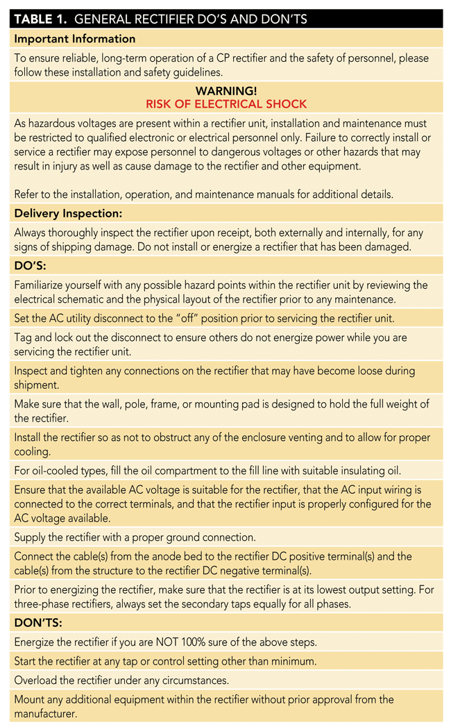
General Rectifier Do’s and Don’ts
The original article includes the following reference table for general rectifier safety and operation.
Why Routine Rectifier Monitoring Matters
Routine monitoring helps verify that a rectifier remains in operation and provides an opportunity to identify electrical, environmental, or physical problems that could affect the CP system.
Inspection frequency may be established by regulation, system requirements, owner procedures, or company policy. Applicable requirements should always govern the monitoring schedule.
VISUAL INSPECTION
- Physical cabinet damage
- Evidence of overheating
- Damaged components
- Environmental intrusion
- Pest activity or nests
- Meter readings and settings
SYSTEM CHECKS
- Output voltage
- Output current
- Meter accuracy
- Tap settings
- Applicable structure-to-electrolyte measurements
- Remote monitoring status, when installed
REMOTE MONITORING
Remote monitoring can provide valuable visibility into rectifier status, especially at difficult-to-access locations. It should be incorporated into a broader inspection and maintenance program appropriate to the asset and applicable requirements.
Before Opening or Inspecting a Rectifier Cabinet
Personnel should first evaluate the work area and look for environmental or electrical hazards. Conditions such as standing water, damaged equipment, unusual sounds, scorching, overheating, or animal activity can indicate that additional precautions are needed.
Use appropriate electrical test equipment and required PPE rather than relying on physical contact with the cabinet to determine whether an electrical hazard is present.
Rectifier Maintenance and Troubleshooting
The original article identifies neglect, age, and lightning as major contributors to rectifier failure. Other common problems can include failed meters, loose electrical connections, blown fuses, damaged structure or groundbed leads, and failed internal components.
Troubleshooting should be performed systematically by qualified personnel using the rectifier manufacturer’s maintenance guidance and applicable electrical-safety procedures.
COMPONENTS THAT MAY REQUIRE EVALUATION
- Circuit breaker
- Transformer
- Rectifier stack
- Voltage and current meters
- Fuses
- Choke and capacitors
- Lightning and surge protection
- Structure and groundbed lead wires
- Electrical connections and terminals
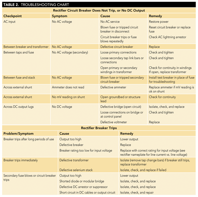
Rectifier Troubleshooting Reference
The original article provides this troubleshooting chart as a technical reference.
Common Rectifier Problems
Several operating conditions can indicate a problem with either the rectifier itself or other parts of the cathodic protection circuit.
OUTPUT ISSUE
Voltage present, but little or no current
Possible causes can include an open or damaged output circuit, deteriorated groundbed performance, lead-wire problems, or other system conditions. Qualified personnel should isolate the cause using approved test procedures.
CIRCUIT PROTECTION
Blown fuse or tripped breaker
A power surge may be one possible cause, but repeated operation of protective devices can indicate a fault requiring further diagnosis rather than repeated resetting or replacement.
ENVIRONMENTAL CONDITIONS
Pests, debris, moisture, and blocked ventilation
Animal nests, insects, debris, water intrusion, or restricted ventilation can create maintenance and safety concerns and may contribute to overheating or equipment damage. Cabinet openings and ventilation should be maintained according to the equipment manufacturer’s recommendations.
IMPORTANT DISTINCTION
Monitoring a rectifier is not the same thing as repairing one.
Routine observations and readings may identify that a problem exists. Internal electrical troubleshooting, component replacement, and repairs require appropriate qualifications, procedures, test equipment, and electrical-safety controls.
The Role of Rectifier Maintenance in Cathodic Protection
Effective cathodic protection can help extend the service life of metallic infrastructure by reducing corrosion. In an impressed current system, the rectifier is a critical part of maintaining that protection.
Routine monitoring, good housekeeping, appropriate surge protection, timely maintenance, and qualified troubleshooting can help support reliable rectifier operation over the life of the CP system.
KEY TAKEAWAY
A cathodic protection system can only provide its intended protection when its critical components are operating properly.
Monitoring the rectifier helps operators identify problems early and maintain continuity of protective current.
ORIGINAL ARTICLE & REFERENCES
The author acknowledged support from Integrated Rectifier Technologies, Inc.; Universal Rectifiers, Inc.; ERICO International; Amcorr Products & Services; Tim Jenkins; and Don Olson.
1. “General Rectifier Do’s and Don’ts,” Integrated Rectifier Technologies, Inc.
2. “Rectifier Troubleshooting,” Universal Rectifiers, Inc.
This article is based on CORROSION 2015 paper no. 5667, presented in Dallas, Texas.
This article by Eric S. Langelund first appeared on MaterialsPerformance.com on May 4, 2020. Reprinted with permission.
ABOUT THE AUTHOR
Eric S. Langelund
At the time of the original article, Eric S. Langelund was a project engineer at Piping & Corrosion Specialties, Inc. His work included cathodic protection and corrosion-control consulting, with experience in CP system testing, troubleshooting, design, installation, stray DC mitigation, and induced AC on pipelines. He holds a B.S. degree in materials engineering from the University of Wisconsin–Milwaukee.
MATERIALS PERFORMANCE
Explore More Corrosion Control Resources
Find technical articles, field experience, research, and practical information on cathodic protection, coatings, corrosion engineering, and asset integrity.
EXPLORE MORE
Cathodic Protection Resources
Corrosion Reference Library →
Cathodic Protection Education →
AMPP Education →
Materials Performance →

Have photos or videos from the field? Submit them to AMPP →