Effective CP System Proves Important in Protecting against MIC in Oil Tank
STORAGE TANKS · CATHODIC PROTECTION · SOIL-SIDE CORROSION · MIC · FAILURE ANALYSIS
Four aboveground storage tanks failed within a two-year period only seven years after a refinery was commissioned. The damage was concentrated on the soil side of the tank bottoms—even though the tanks had an impressed current cathodic protection system.
A failure investigation traced the problem to a combination of inadequate cathodic protection distribution, severe localized underdeposit attack, probable microbiological involvement, and water intrusion beneath the tank floors. Together, those conditions produced extraordinarily high reported corrosion rates of approximately 1 to 2 mm per year.
THE FAILURE CHAIN
Uneven Cathodic Protection
+
Water Intrusion Beneath the Tank
+
Deposits & Localized Corrosion Cells
+
Probable Microbiological Activity
↓
Rapid Localized Tank-Bottom Perforation
Four Tanks Failed in Only Seven Years
The refinery’s aboveground storage tanks were constructed with 8-mm-thick uncoated carbon steel bottom plates.
Within seven years of commissioning, severe soil-side corrosion had damaged four tank bottoms badly enough to cause failures over a two-year period.
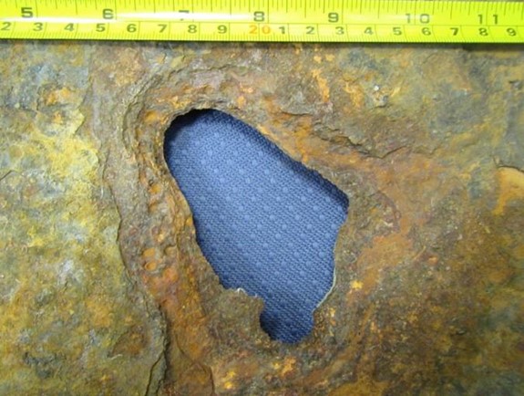
Examination of the damaged plates revealed large, deep pits beneath orange-red corrosion tubercles composed primarily of iron oxide corrosion products.
WHY THE FAILURE WAS UNUSUAL
The reported corrosion rate—approximately 1 to 2 mm per year—was severe enough that an 8-mm carbon steel floor could experience major localized loss in a relatively short period. That pointed investigators toward more than ordinary uniform soil-side corrosion.
The Tanks Already Had Cathodic Protection
The underside of each tank bottom was protected by an impressed current cathodic protection, or ICCP, system.
The system used a mixed-metal oxide grid anode installed beneath the tank bottom. The anode grid was located between a high-density polyethylene secondary containment liner and the tank floor, which rested on an approximately 75-mm-thick sand pad.
Because the underside of the carbon steel floor was uncoated, the CP system had been designed for 100% bare steel surface area.
CATHODIC PROTECTION IS NOT JUST ABOUT HAVING AN ANODE
Anode System
+
Electrical Distribution
+
Current Reaching the Entire Structure
↓
Adequate Polarization Where Protection Is Needed
The CP Survey Revealed Significant Underprotection
A detailed cathodic protection survey was conducted approximately six months after the sequence of tank failures.
According to the historical investigation, none of the surveyed tanks achieved the protection criterion referenced in NACE SP0193-2016 of an instant-off potential of –850 mV relative to a copper/copper sulfate reference electrode.
Measured instant-off potentials ranged from approximately –200 to –800 mV versus CSE, with an average of about –450 mV across the tanks.
Those results indicated that substantial portions of the tank bottoms were not receiving the polarization intended by the CP design.
HISTORICAL CRITERION
The –850 mV instant-off value is included here because it was the criterion cited in the original failure investigation. Current projects should use the applicable current AMPP standard, governing specification, qualified CP design, and appropriate evaluation criteria for the structure and environment.
Why Was the Current Distribution So Uneven?
Investigators then examined the design and operation of the ICCP system to understand why so much of the tank bottom remained underprotected.
The paper identified deficiencies involving the depth and spacing of the MMO grid anodes and the distribution of power-feed cables.
Current and voltage attenuation along portions of the anode grid produced a nonuniform potential profile. Areas farther from the power-feed points did not receive enough current to develop the required level of polarization.
In other words, the system was energized, but the protective current was not being distributed effectively across the entire tank bottom.
THE PROBLEM WITH NONUNIFORM CURRENT DISTRIBUTION
Adequate Current Near Feed Points
→
Increasing Attenuation Across the Grid
→
Insufficient Current at Remote Areas
↓
Localized Underprotection
But Inadequate CP Did Not Explain Everything
An ineffective or poorly distributed CP system can leave steel vulnerable to corrosion, but the investigators concluded that underprotection alone did not fully explain the unusually severe localized attack.
A failed tank-bottom sample was therefore sent for metallurgical and corrosion-product analysis to identify other mechanisms that may have accelerated the damage.
FAILURE ANALYSIS SHOULD FOLLOW THE EVIDENCE
Finding one deficiency does not necessarily mean it explains the entire failure. Severe or unusual corrosion morphology may require metallurgical examination, deposit analysis, environmental evaluation, CP review, and other evidence to understand the interaction of mechanisms.
The Pits Were Hidden Beneath Layered Corrosion Deposits
X-ray diffraction analysis showed that the orange-red tubercles consisted of porous, layered corrosion products composed mainly of iron oxides, with magnetite also identified.
The deposits covered areas of severe localized pitting rather than a relatively uniform loss of metal across the tank bottom.
Analysis of flakes taken from the scale over the pits indicated probable involvement of iron-oxidizing bacteria, or IOB.
UNDER A DEPOSIT, THE ENVIRONMENT CAN CHANGE
Deposit Forms on Steel
↓
Local Oxygen & Chemistry Differ
↓
Differential Aeration Cell Develops
↓
Localized Corrosion Can Accelerate
Where Microbiology May Have Fit Into the Failure
Microbiologically influenced corrosion, or MIC, is not a single corrosion mechanism. Instead, microorganisms can alter local conditions at a metal surface in ways that influence electrochemical corrosion processes.
In this case, the morphology and deposit analysis suggested probable iron-oxidizing bacterial activity.
Iron-oxidizing bacteria can contribute to the formation of orange-red iron oxide and hydroxide deposits. Those deposits can help establish localized chemical and oxygen differences beneath the tubercle, potentially contributing to differential aeration and underdeposit attack.
The investigation therefore treated microbiological activity as part of a broader corrosion environment rather than as an isolated explanation for the tank failure.
MIC IS NOT IDENTIFIED BY COLOR ALONE
Tubercles, pits, or unusual deposits may suggest possible microbiological involvement, but reliable failure analysis requires supporting evidence. Corrosion morphology, environmental conditions, deposit chemistry, microbiological evidence, and other mechanisms should be evaluated together.
Water Intrusion Created the Environment Corrosion Needed
The investigators also identified a persistent source of moisture beneath the tanks.
Water—reportedly originating primarily from leaking fire-water sprinklers—was able to enter through gaps between the annular plate and the foundation.
That ingress introduced moisture beneath the tank floor along with corrosive species such as chlorides and sulfates and potentially microorganisms.
With bare carbon steel, ineffective CP in portions of the floor, retained moisture, deposits, and aggressive contaminants present together, localized attack was able to progress rapidly.
MOISTURE WAS A CRITICAL PART OF THE SYSTEM
Water Entry
↓
Electrolyte + Contaminants + Microbiological Transport
↓
Persistent Corrosive Environment
↓
Accelerated Soil-Side Attack
The Tank Bottom Had No Backup Corrosion Barrier
The underside of the tank floor was bare carbon steel. That meant the ICCP system represented the primary engineered corrosion-control method for the soil-side surface.
When portions of the floor did not receive adequate protection, those areas were exposed directly to the wet and increasingly aggressive environment beneath the tank.
The case demonstrates why corrosion protection should be evaluated not only by whether a system exists, but by whether it is actually functioning across the entire area it was designed to protect.
INSTALLED DOES NOT MEAN EFFECTIVE
Cathodic protection performance has to be verified through appropriate testing, monitoring, interpretation, and maintenance. A functioning rectifier or energized anode system does not by itself demonstrate that every critical area of the structure is adequately protected.
What the Failure Investigation Revealed
No single observation explained the entire failure. Instead, the evidence pointed to several interacting conditions.
KEY FINDINGS
- The tank bottoms experienced severe localized soil-side corrosion rather than simple uniform thinning.
- The ICCP system did not provide adequate polarization across substantial portions of the tank bottoms.
- Anode configuration and power-feed distribution contributed to uneven current distribution.
- Orange-red layered corrosion tubercles covered deep localized pits.
- Deposit analysis indicated probable iron-oxidizing bacterial involvement.
- Water ingress created a persistent electrolyte beneath the tank floor.
- Incoming water introduced or transported corrosive species including chlorides and sulfates.
- The steel underside was uncoated, leaving CP as the primary soil-side corrosion-control method.
The Broader Lesson Is About Corrosion Management
This case is a reminder that corrosion-control systems cannot be treated as independent pieces of equipment.
Tank foundation design, moisture control, drainage, cathodic protection, electrical distribution, environmental conditions, materials, inspection, monitoring, and maintenance all affect the actual corrosion environment beneath the floor.
A weakness in one part of the system can become much more consequential when another protective layer is also compromised.
THINK IN SYSTEMS
CP Design + Moisture Control + Foundation Details + Monitoring + Inspection
↓
Better Control of Tank-Bottom Corrosion Risk
BOTTOM LINE
The premature tank failures were not simply a case of “cathodic protection failed.” The investigation showed how inadequate current distribution, water intrusion, underdeposit conditions, corrosive contaminants, and probable microbiological activity combined to create severe localized soil-side attack. Effective tank-bottom protection depends on controlling the entire corrosion environment—not merely installing a CP system.
HISTORICAL CASE STUDY
This article summarizes a historical tank-bottom failure investigation based on NACE CORROSION paper no. 9025. The cited cathodic protection criteria, standards, system configuration, and investigative conclusions reflect the project and publication at that time. Current storage tank projects should follow applicable current AMPP/API standards, project specifications, qualified engineering guidance, and site-specific operating requirements.
Source
Adapted with permission from Materials Performance. Based on NACE CORROSION paper no. 9025, “Premature Failure of API 650 Oil Storage Tank Bottom Plates Due to Soil Side Corrosion,” authored by N. Al Abri, J.R. Nair, A. Al Ghafri, and F. Al Mawali.
LEARN MORE
Cathodic Protection Is a System That Has to Be Verified
AMPP resources cover cathodic protection design, inspection, testing, corrosion mechanisms, storage tanks, and the skills needed to evaluate whether protection systems are performing as intended.

Have photos or videos from the field? Submit them to AMPP →